
Bridgeport Power Feed to Z-Axis
Now that the cylinder blocks have been recovered my mind has turned to their machining. They are too big to bore on the lathe so the Bridgeport is my only option if I am to keep the work in house. I have seen cylinder blocks done on horizontal mills but I don't have the horizontal attachments for my machine. the tricky bit would be the vertical boring and would need to be done using a custom made boring bar. The quill feed on the machine has only two speeds and has always seemed a bit harsh for my liking so I decided to purchase an Align power feed for the Z axis.
This would give me an infinite variable feed range and also the advantage of rapid feeds to the Z axis. I had previously fitted one to the cross travel many years ago so though this would be an ideal excuse to purchase one for the Z axis. Once I got the box open I found the "destructions" were exactly the same as I had received years ago with the same errors and Tiwanglish. So as a picture tells a thousand words and if your thinking of fitting one, it took me about two hours to do.
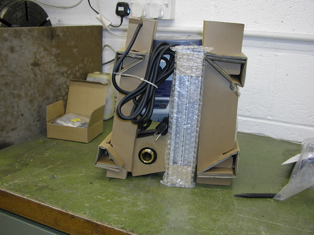
Easy way to get everything out was to tip the box upside down
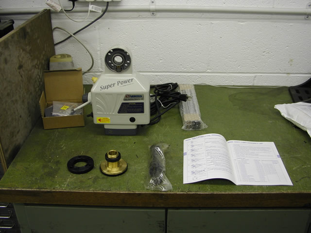
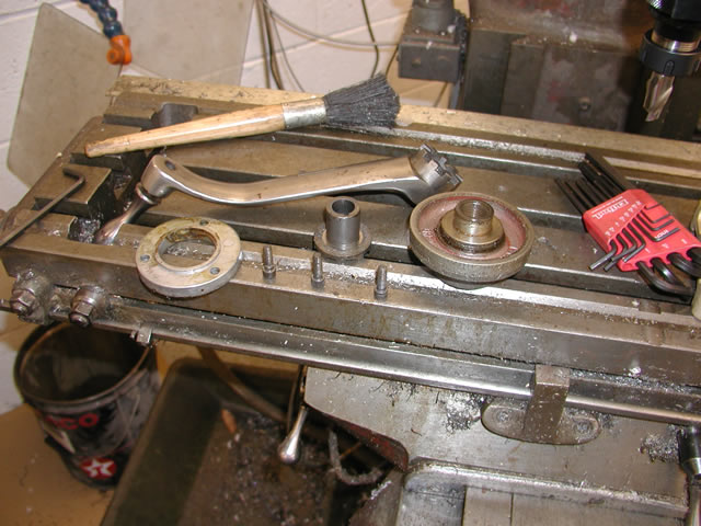
The main ingredients, from back left, the box of trip dogs, shims and hardware. The feed itself with the trip guard to the right. From front left the mounting ring, the drive gear, new shaft and the instruction book.
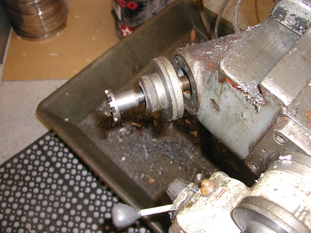
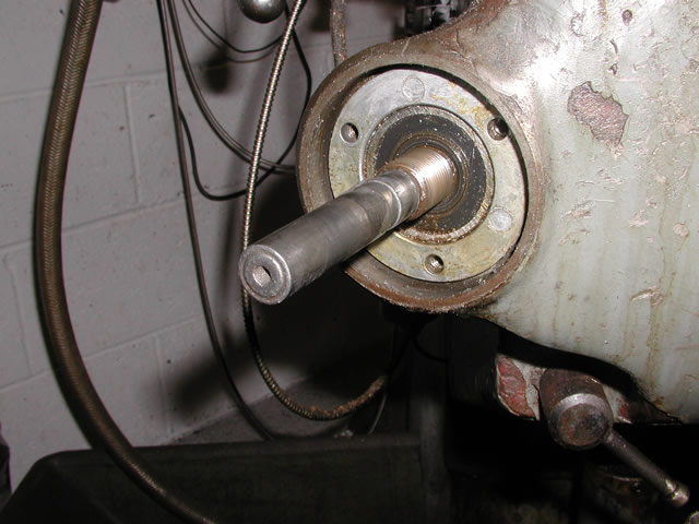
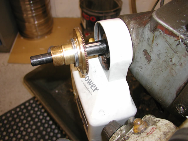
First thing to do is remove the old drive dog and the graduated bezel. It did not look this dirty in real life!
Next job was to remove the three screws and take the aluminum retaining plate off
All of the parts from the old drive mounting.
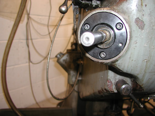
The new plate fitted the hole at 4 o'clock is one of two for the drive to bolt too.
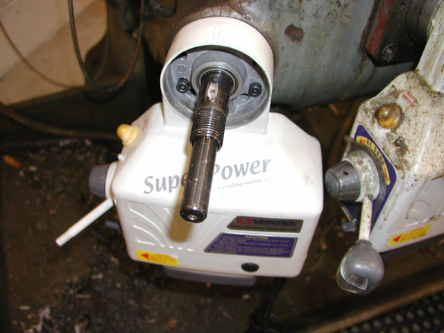
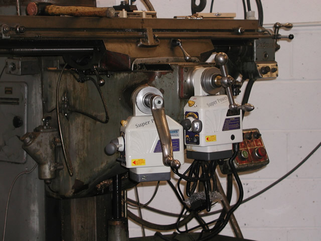
Because I already had a drive on the cross feed when I tightened up the new one it fouled the knob on the right. To overcome this I cleaned out the two holes slightly to allow the new box to rotate clockwise to give the clearance I needed.You can see a bit of hole peeking above the left hand alan screw.
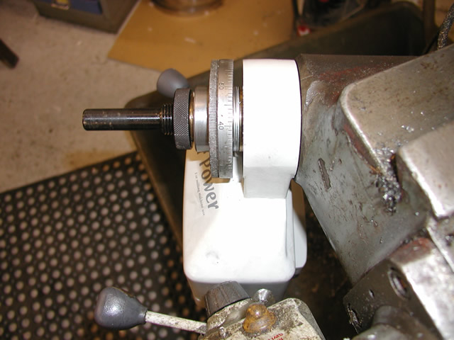
The new extension shaft has also been fitted in this view, a hole has been drilled through both shafts and a role pin fitted as can be seen. Note this is the wrong place for the pin according to the instructions but I would need to have read them to know that! The cross feed roll pin fits in this position which is why I did not check.
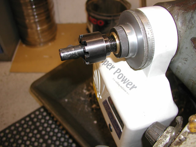
The new drive gear which meshes with the pinion which can just be seen at the bottom . This slides over the key and if required you can fit shims in front of it to get the right mesh if needed. The shims behind the gear are for the bezel
The lock nut behind the bezel, if your not careful it will lock the bezel against the face of the drive box. Hence the shims behind it. Also once the new drive nut is fitted (shown below ) it pulls everything together and can increase the interference between the bezel and drive box face so add an extra shim or two just to be safe.
The new drive nut locks hard against the bronze face of the gear and pulls the whole assembly tight. Hence the need to have enough shims behind the bezel.
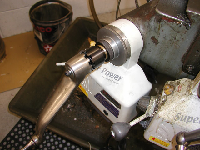
The old handel is secured with an alan screw and a spring to keep it out of mesh when the drive is active.
So that's it, I had the drive working in about 2 and a half hours the only work needed that was not in the box was drilling the dowel pin and changing the American three pin plug for our 110V one. One thing to note if the wires are in American colours then for our side of the pond they are :-
White - Neutral
Black -Live
Green Earth.
You also have the option of fitting a limit switch track to the machine, but I don't see the need of it as I have not fitted one to the cross travel and don't intend leaving the machine unattended anyway.