
Buffer Beam
The buffer beam could probably have been manufactured by some of the more experienced builders by fabrication, but as usual I decided to go my own way. In this case the plan was a cast front end which would bolt into the frames and once the holes had been filled in would take on the appearance of the one piece cast frame of the original.
Machining the pocket to take the buffer beam after casting
Perhaps a word on nomenclature would be appropriate as whilst the English buffer beam might be accurate for a UK locomotive. This one clearly did not have any buffers and I suppose would be called a pilot beam by our American friends. Fitted with both knuckle couplers and a tube pilot it's probably more accurate as well. But as I don't know what North British called it I will settle for my own familiar English one.
So first thing was to set Terry off turning my drawings into a negative and producing another of his first class patterns. Then off to the founder, Geoff, who is also getting very good at working out where Terry's cores fit.
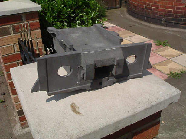
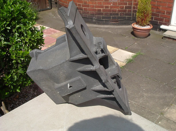
Two Shots of the first casting as you can see, Terry had done a first class job getting all the detail of the original casting into his pattern. I also prefered the patina of the sand casting as it looked more real than a steel fabrication ever could.
So where to start? Well as usual I wanted a flat datum to start from and to do as much machining as possible at one setting to reduce the amount of errors. Since I became such an expert at generating errors.
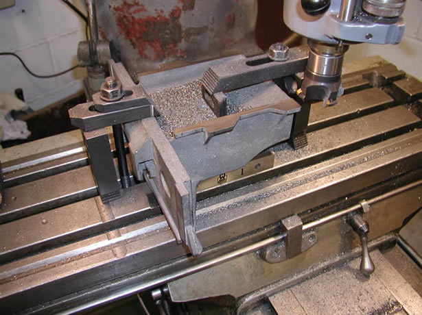
The two wings on the top of the casting were used to bolt a large balance weight onto the full size locomotive and in my case were ideal to select as the datum as the most important machining needed to be done with the casting upside down. So just a light skim was all that was needed to prepare them for securing to the Bridgeport table.
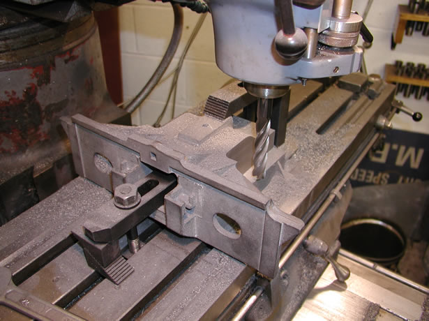
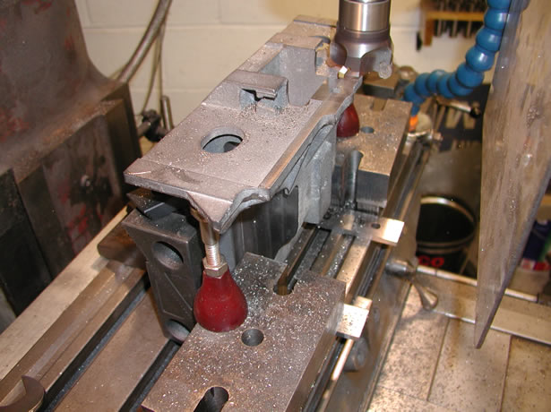
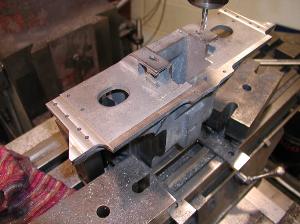
So the casting was set on the table and squared off from the front face, as it was the longest side and would give the best starting point to work from. I then used an electronic edge finder to centre the quill on the Bridgeport with the center of the casting along the Y'-Y' axis. From here I could machine each side and ensure I was taking the same amount off. Then run a facing cut off the rear to set the length and provide a datum when it came to machining the front face.
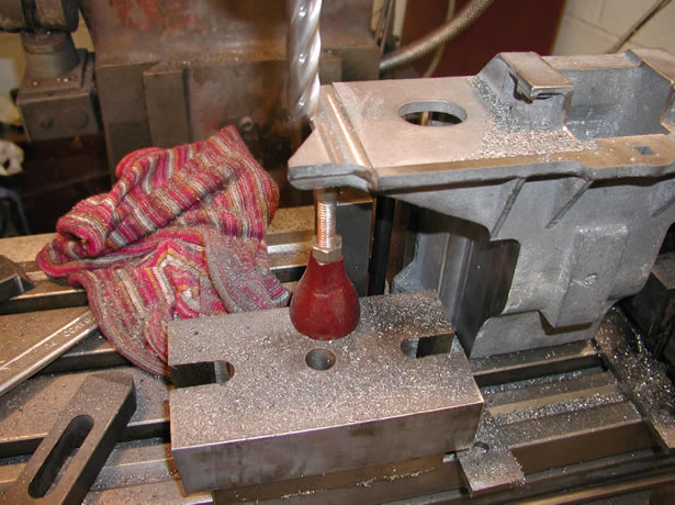
As can be seen from these two images the casting has been machined to length and the basic pockets had been machined on the sides. All done from the one clamp position so I was fairly sure they would be square.
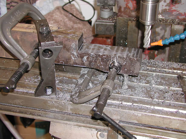
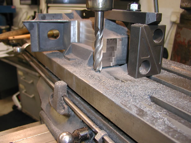
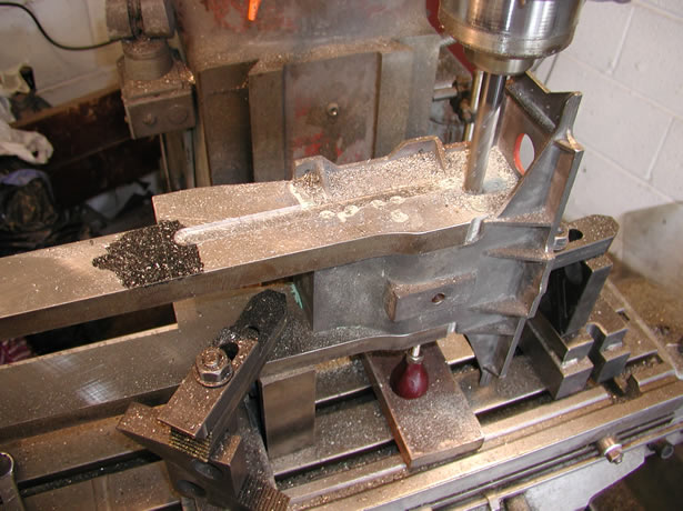
Once the sides had been machined it was time to form the front of the pocket and also time to admit to another mistake, or at least lack of thought on my part. Unfortunately it's a lot easier to machine things on the drawing board than it is in real life and the length of the pockets I had on the drawing did not need to be as long as I designed them.
This problem showed itself in getting a tool in to machine near the front of the casting as can be seen the cutter was a mile out of the quill and was just able to get the corners cut out. In reality the pocket could have ended at least an inch back from where it was and would have been much easier to machine.
All a bit tight and a battle to get the pockets machined as per the drawing. I also had chamfered the frames to allow for the radius of the cutter in the plane so once done the pockets should take the frames no problem.
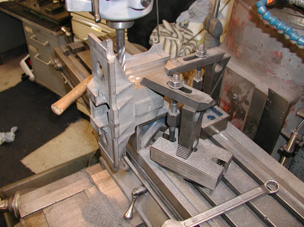
Extentions on the clamps, tool out as far as it would go, all a bit on the edge and not an entirely comfortable machining set up.
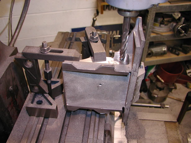
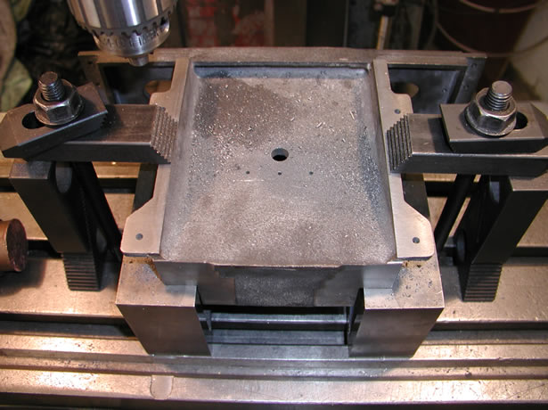
Next job was to bolt the casting on its back to machine the front face. For this I set it up off the machined face from the first set up and once again with the edge finder set the quill up in the middle with respect to the sides. There are basically three areas to machine, one is where the pilot frame bolts to and the others is where the steel wings bolt. Nothing to complicated and once the centre of the casting had been determined it was all down to the digital read out.
Cutting the sides where the wing extentions fit.
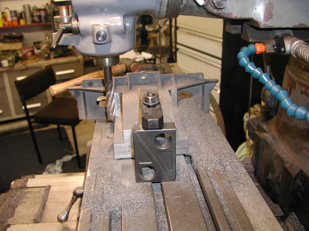
Milling the holes for the coupler hangers.
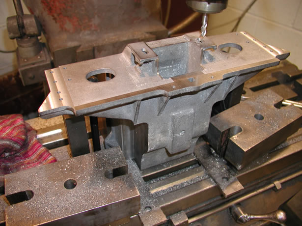
Once the faces had all been machined I swapped the cutter for a drill chuck and setting everything off the datum's established used the digital read out to locate all the hole positions. Hoping that everything else would line up with the laser cut wings when I came to fit them.
All the drilling now done, 2 holes are for the grab handles, the four holes are for brackets that carry the tube pilot as do the two horizontal holes as well.
The last job on the casting was to drill the four holes that were used to bolt the counterweight on to the frame. I also needed to drill three tapped holes for a piece of angle, which supports the catwalk when it gets fitted.
Finally the casting was bolted into the frames, and the holes were filled with a bit of plastic metal. Once cured the frame was set-up on the mill to reduce the width of the front, around the buffer casting area. According to the drawing the frames narrowed at the front so I marked off the starting point and using a ball cutter, which approximated to the radius of transition as the frames narrowed, took a skim off both sides to finnish off the job.
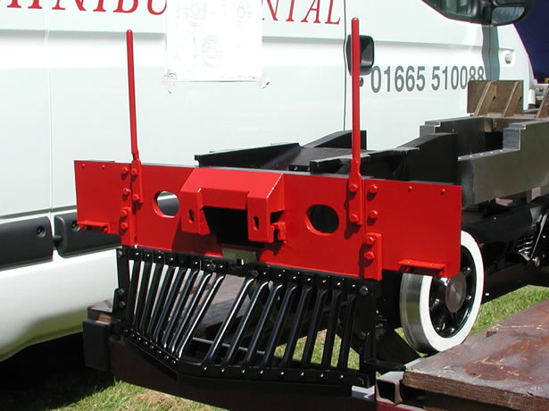
Bolted into the frames and with the wings, grab handles and tube pilot fitted, it does not look bad. I had a right job getting the copper tubes to take the paint only to find recently a picture of a 25 with the copper tubes left unpainted and polished up, which looked a treat. Never mind I am sure I will end up knocking it off one day so plain copper may appear.