
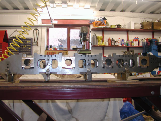
Main Driver Cannon boxes
The main driver boxes were just bigger brothers of the front truck's and as such I thought would not be that difficult to machine. Although a four axle locomotive only three axles had the same box. The main driver is larger I guess to accommodate the higher forces and hence larger bearings.
For a start the first thing was a decision on cost, and if I was going to make two patterns or one. Well I decided after drawing both boxes up I could get away with one machining down the sides for the three smaller ones. So once that decision was done it was off to Terry with the drawing and waiting for the pattern to return.
The next thing was a material choice and as on the front truck I went for bronze-ish material which will be the last time I do that. The stuff is murder to machine and if I ever cast anymore they will be cast iron as its much easier to work with.
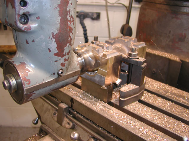
First job was to get a datum to work from, there are four pads on the bottom of the casting. So a quick skim across them set up the base point for the rest of the work.
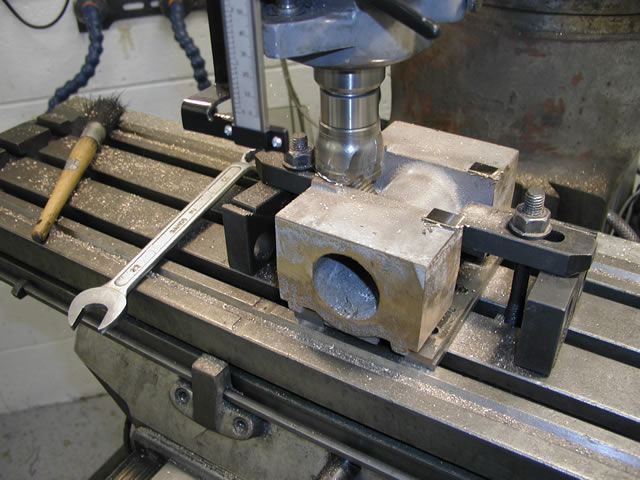
Machining the pads on the bottom of the box
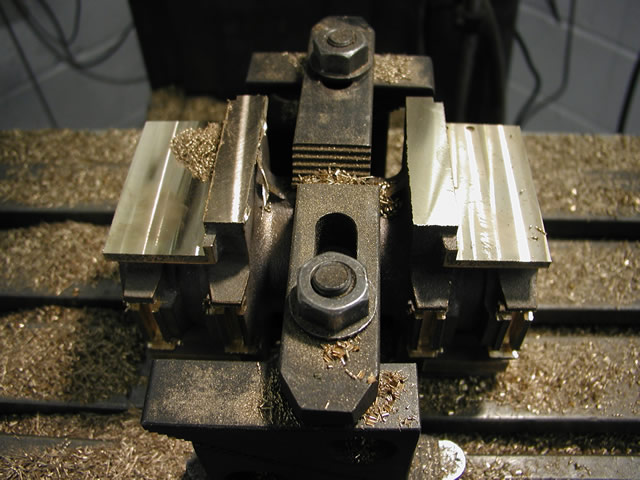
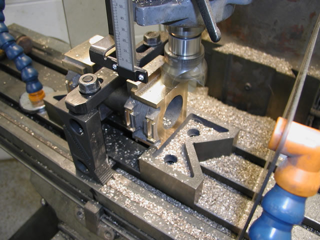
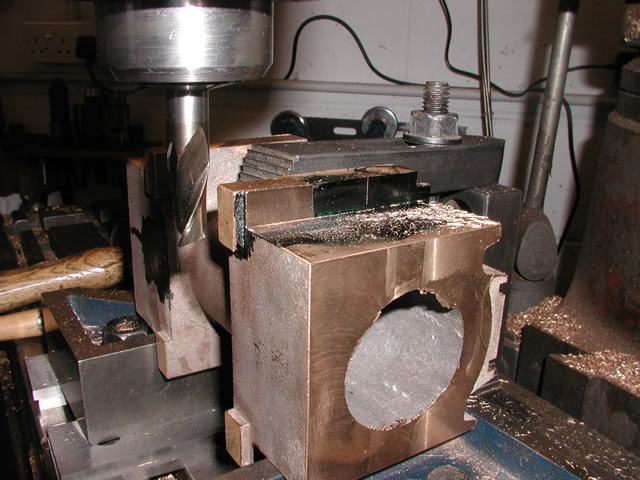
Once all the boxes were machined I then set the box up to machine the slots for the suspension blocks.
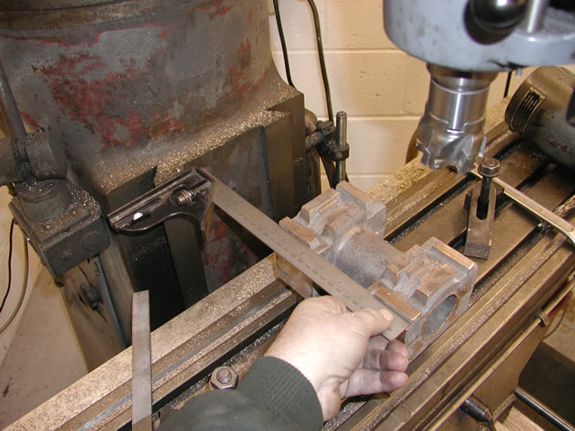
Surprisingly this is not as easy as it seems and I could have done with a third arm just to hold the square against the mill and the rule. Still leaving one spare to move the box around. Somewhere I have seen a little fixture that clamps into the dovetails for the knee and had a square attached so all you needed to do was adjust the item you were squaring up. Sadly like lots of things you can never find the reference when you need it.
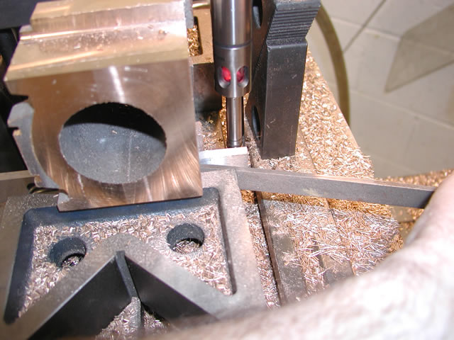
Once square, the trusty electronic edge finder came into its own again. Working from the center part of the casting Ii was able to set up a datum from the center in both the X and Y directions. Setting the digital read outs to zero, my intention was to work away from them to carry out all the machining.
This grandiose idea of machining everything from there in one set up. Was a great idea which after loads of fiddling and set up problems I finally abounded in favor of a multi-set up approach. so first job was the slots for the suspension blocks
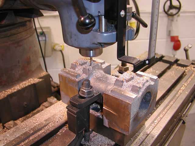
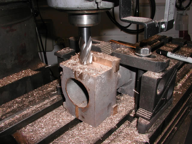
5mm slot drill milling slots
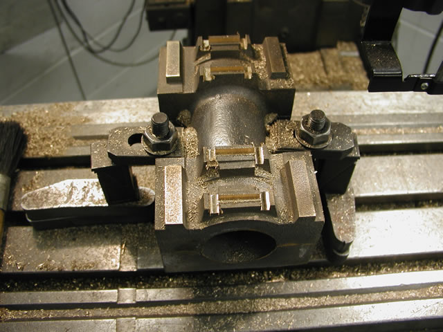
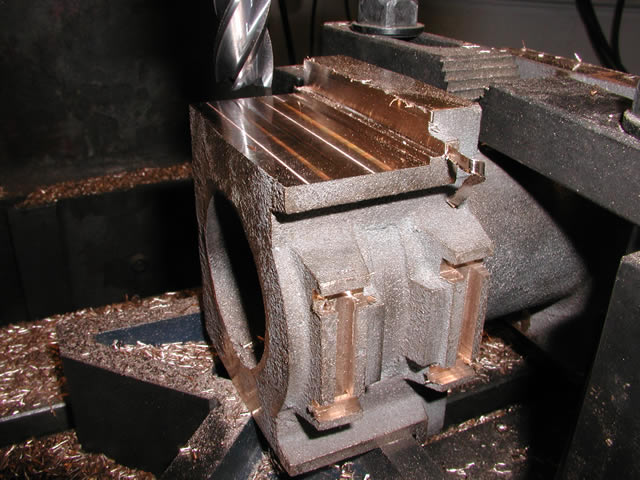
All slots machined
I used a 5mm cobalt cutter for the slots and for the 8 boxes ended up using 5 cutters. They seemed to blunt very quickly and snap off quite disconcertingly. However after I had snapped a couple I became almost used to the clunk as another one bit the dust.
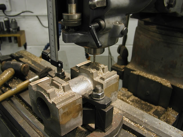
I had found that one of the vagaries of machining this material that multi-pass operations always seemed to leave a ridge between cuts. I am not sure why this happens but I had a large tipped tool that would do the faces in one pass. So This became my weapon of choice, mounted in the right angle attachment . Using that would sort the ridge out but made getting the faces correct relative to the center point of the casting a bit of a problem. So to get round that I used a cutter mounted vertically to machine the front and side face to the correct width and length, well have of it if you see what I mean. Then all I had to do was touch on the the horizontal cutter to get the faces to the correct dimension.
Machining the front and side face datum's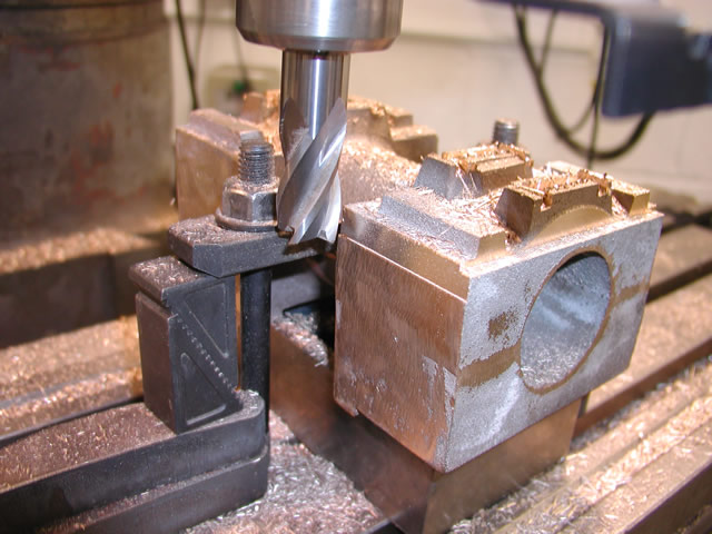
one the front and side faces had been machined it was then time for the right angle attachment and full machining of the two faces. once this was done the first set up was complete and it was onto machining the first pedestal side.
So using the two faces I had now machined the next job was using the machined face to sit on, machine the other side and start forming the faces that mate with the frames.
Setting up the front face square
First skim across the side
Starting to form the pedestal face
Un fortunately the tipped tool had a small radius on the tips corner which i needed to get rod of. to do this I used a sharp new end mill for the final cut across the face and edge. only taking about 5 thou off I found as long as it was very sharp I had no recurrence of the ridge problem.
Two faces full formed
Both sides done.
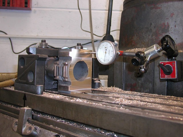
I now had two one side done to the correct depth and inner frame width, so the next job was to turn it over and machine the other faces. The next conundrum was how to get the two faces of the pedestal on each side parallel with each other. I am guessing there are a number of ways i can think of a couple but the way I did it was using the edge finder to establish the datum. Unfortunately I needed three arms again so came up with the following solution.
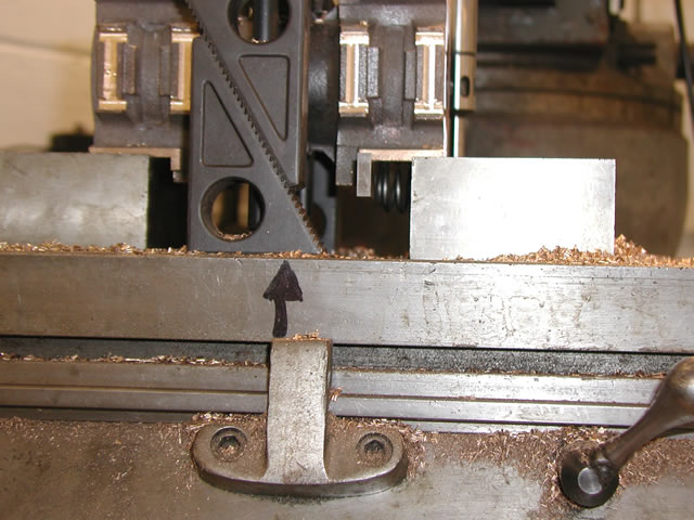
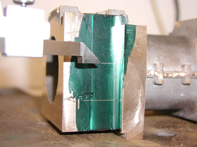
Parallel held in place by spring
What I did was put a parallel against the previously machined face. Unfortunately to hold the paralleled in place and turn the hand wheel to move the table I was a hand short. So to overcome this I put a spring on one side to hold the parallel then used a lever on the opposite side to hold it firmly allowing my other hand to move the table till the edge finder sounded off.
Holding parallel against face and touching on with edge finder.
This worked a treat all I had to do was zero the digital readout when the edge finder touched on. Then just run the cutter up to that reading to ensure both faces top and bottom were in line. The opposite side machining then was just a repeat of the previous work. One other way would have been to clock the v block I was using to sit on square to the table, Then push the machined face hard against this, then touch on the face of the v block and work from there. This would have been less setting up in hindsight but we where were we where.
Rough cutting to depth
Two shots final cut to width and depth 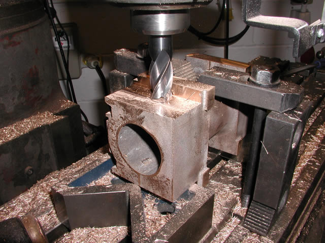
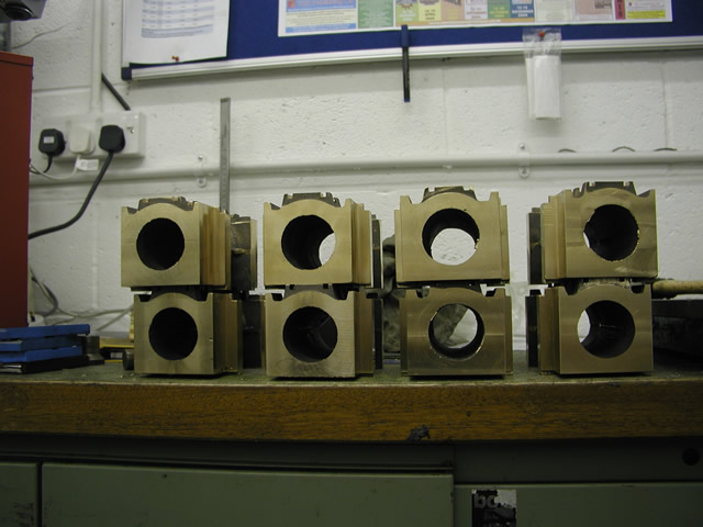
All done
Next job was to drop the boxes into the pedestal gaps and see how they fitted. I was expecting a bit of filing but had slightly more than that to do. After spending loads of time making sure everything was the right size and all the x beams were accurate when I came to try the boxes in There was more than a bit of filing required. Much to my surprise and concern the frames were not parallel but varied very slightly on two of the slots. How to overcome this was a puzzler, there was not much room to get a file in or an air tool in to fettle them up so I decided the frames would have to go back on the mill. Only problem was it was 9 foot long and bloody heavy to move around.
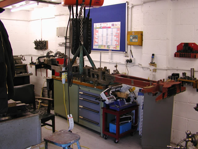
On the electric hoist another eBay purchase making its moneys worth
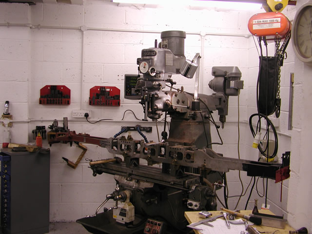
Sitting on the mill I had to remove some of my collet holders on the wall and move some of the cabinets out of the road but I just got it on.
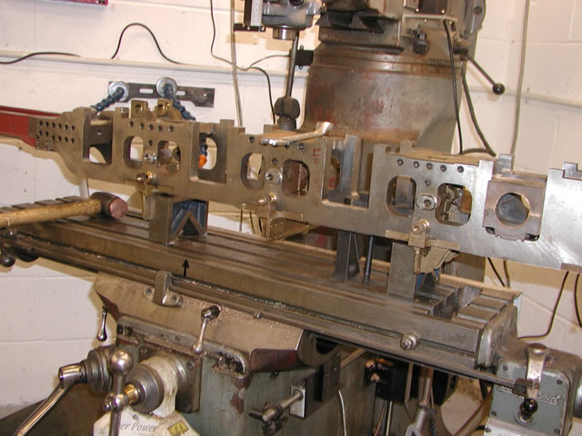
Sitting on the X brackets where they had been machined the whole thing sat nice and square so how did I manage to let the error creep in?
A we bit of machining later and some filing to suite and all the boxes are sliding nice and easily into the pedestal slots.
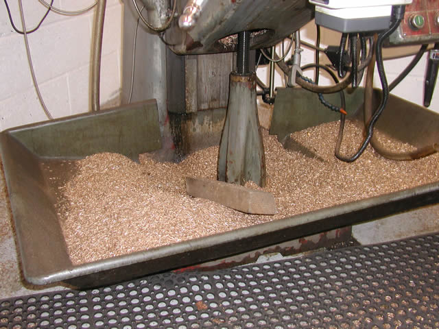
So what's left after all that well plenty of chips that's for sure. So next after spending all that work getting everything in line parallel, the same widths lengths. I had to machine most of it away, to allow for vertical moment. Due to undulations in the track the boxes have to be able to move vertically. To do this as the move upwards they need relieving to allow for the movement. this generally is done but machining a slight angle on the faces in this case 3deg. Although I have seen clever builders machine the face on a rotary table to produce a very large radius across the face.
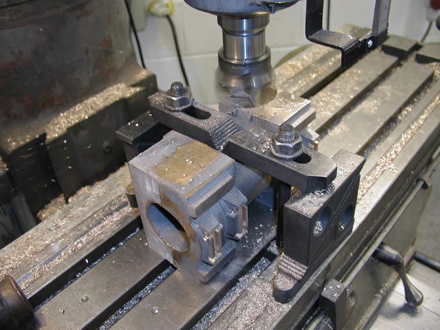
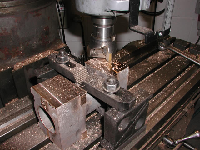
Marking out for the angular cut in thirds across the face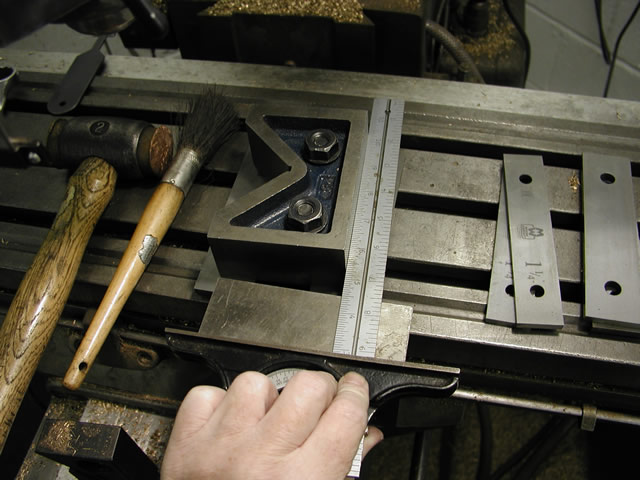
Setting up the V block at 3deg the box will fit flush against this.
Cutting the angle on the face, I did all the faces on one setting then moved it round 6deg to do the other side.
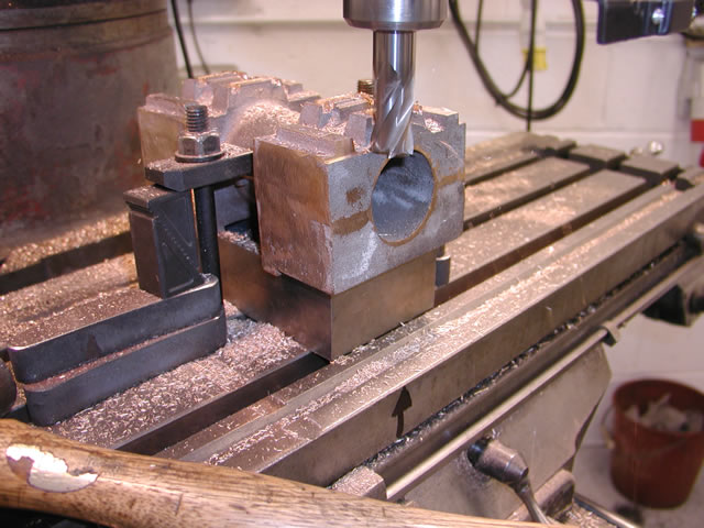
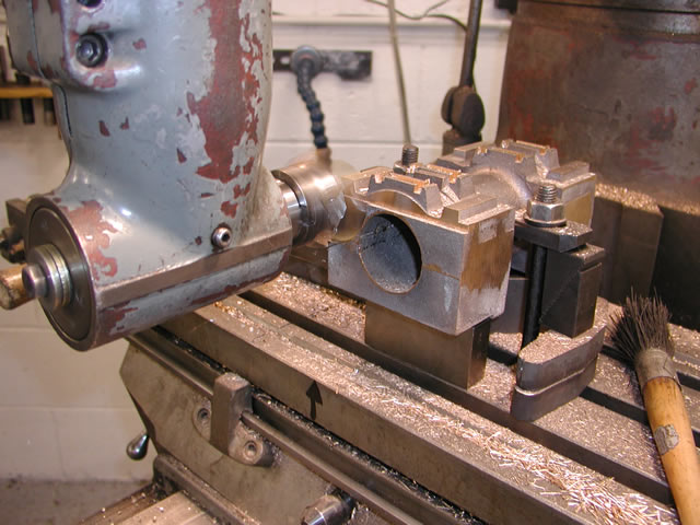
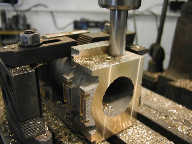
So that was all the machining operations done on the boxes for the outside. The next job was to machine the bores ready for the bearings. To do this I intended to machine up a jig similarly to the front truck. But more of that later