
Cross Beams
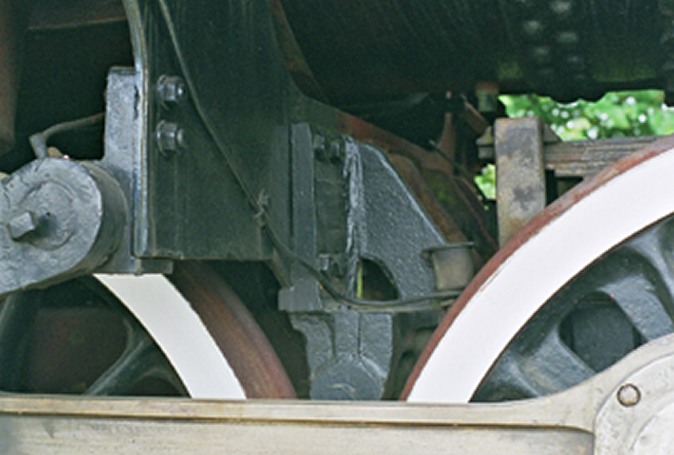
As I said near the start of the frame section, the frame on this locomotive was a one piece casting with all the bracketry cast on, which was then machined after the pour. The frames were made by General Steel castings, an American company and I assume they were cast in the US' then sent over to North British for assembly. To replicate the cross beams I decided to use castings then bolt them into the frame and fill all the holes so it looked as prototypical as possible.
To do this i needed more pattern making and at the time decided to explore the use of Steriolythography, more commonly known as rapid prototyping. The technique uses a UV laser to cure epoxy resin into the shape you need think Star trek replicators and your not far away. Here are a few snaps and explanation to be going on with. Oh, the only other thing you need know is you need to have some sort of 3D drawing package to make the models easier for the machine to read and transform into a tool for the lost wax man.
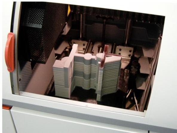
So basically a machine builds up a resin representation of your model a bit like a photo copier but only in 3D. A typical bracket in the machine is shown above. The clever thing is, it produces all the holes pockets and hidden detail for you. So after you get the resin mould you can take it off to the the lost wax foundry where they spray it with a ceramic coating melt out the wax and hey presto your ready to pour in whatever metal your making the casting out of, in my case i used bronze.
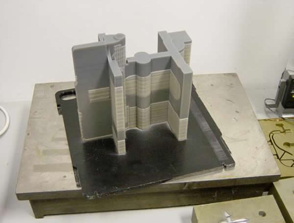
When the process is complete you end up with the resin block you can see above. The darker areas is the part and the lighter areas are basically air. Which the machine fills with a lattice work of resin to aid its build process.
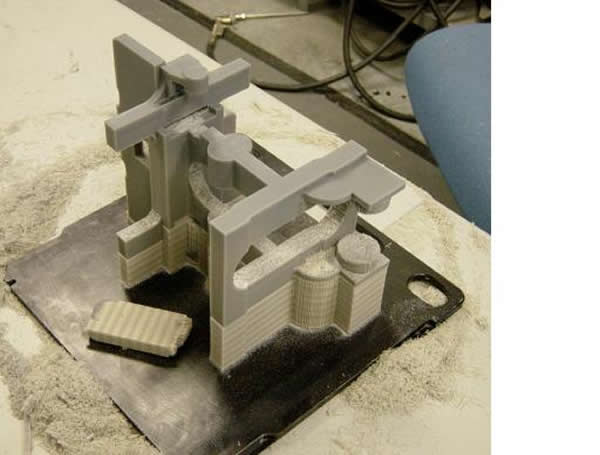
So then the human being comes into play and has to carefully break out all the latticework to leave you with the finished article. The resin is surprisingly tough to break out, though like all fragile things breaks at the drop of a pin if you don't want it too.
Once you have broken out all the bits you don't need you are left with the finished article. After cleaning up it will be ready to go the the lost wax man.
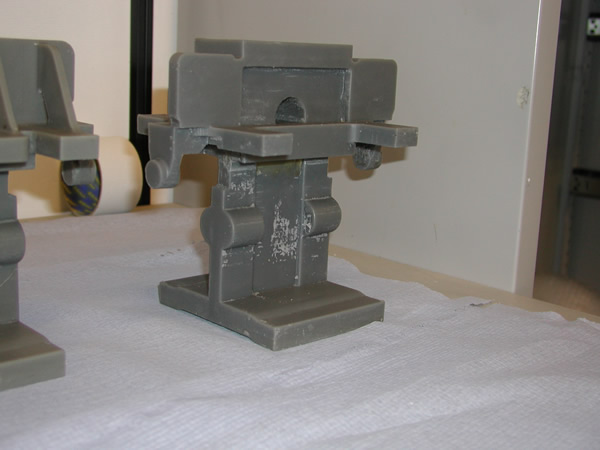
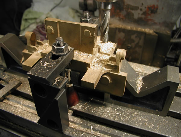
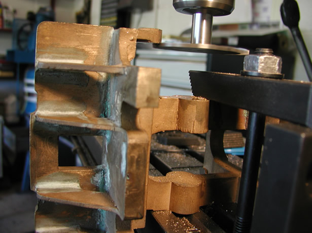
As can be seen above the casting can be very complicated and how we get to the finished machined article like the rear cross beam is detailed below. Essentially all the work followed the same route using the vertical mill to prepare all the machined faces. There are 4 castings for the cross beams The hind casting shown above, the hind intermediate above that and
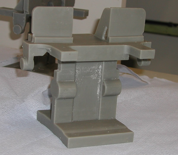
Front intermediate above and the front shown below
Machining the brackets held a number of challenges for me, all around getting repeatability of dimensions and as usual machining as much as I could at one setting. In retrospect once again I wonder if given what i know now I would tackle the job in exactly the same way but we are where we are so the description is as was, not what might have been a better way. Also there had been problems when the wax's were cast and that had resulted in some of the castings being twisted or deformed in some way. This was due to the vacuum being partially lost when the founder did the pour. I had hoped that there would be enough meat in the casting to allow for this, as well as perhaps subjecting some of them to well placed blows with a "mash hammer" Unfortunately after several tries at this I was not able to get one of the castings anywhere near what i wanted.
So to salvage something form the all the cost already sunk into them I decided to cut the one bad casting in half and free up the bottom from the top. This casting the front intermediate would not suffer from being cut so it was not a big problem in making the decision.
Cleaning up where the casting after cutting away the lower half
Machining the lower half to size
So now I had four castings all different but all wanting two things they had to be the same width sit into the previously machined pockets in the frames the same depth and all be the same length, once again to fit the previously machined frame pockets.
To start things off I began with the front beam, setting it up using my edge finder I could then machine the casting to width. Offsetting from the back of the bracket support I could also machine the ends to length. Then finnish it of by machining the arms to the correct thickness.
Cutting the ends to length
Machining the width
Machining the arms to size.
Once all the machining had been done on this front bracket I tried it in the frame pockets and with a little bit of filing it fitted snugly into the previously machined pockets.
The worst affected casting was the rear intermediate boiler support bracket. It was also one with a a lot of metal in the casting so recovering it was important. Prior to machining it looked a bit like it had melted in the heat and I was not sure it would machine up to suite my needs. One way to check was to see how much I could machine off the top face to get it to clean up. Luckily I had left a fair bit on for machining and was able to get about an 80% clean up so breathed a sigh of relief.
Test machining the hind intermediate
The most complicated casting was the hind unit which incorporated the mountings for the brake linkage. Like all the brackets it stated off as a drawing in Solidworks
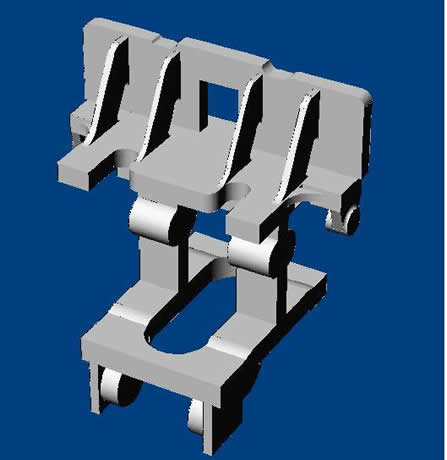
Screen grab from Solidworks of the Hind casting
From there it was off to the thermojet printers and the results can be seen earlier in this section. Luckily although the wax was probably the most complicated with the largest volume of wax used. When it came to casting no problems were experienced and it came out without any distortion or complications.
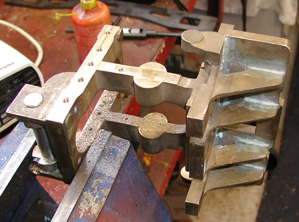
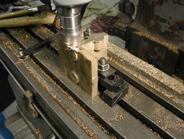
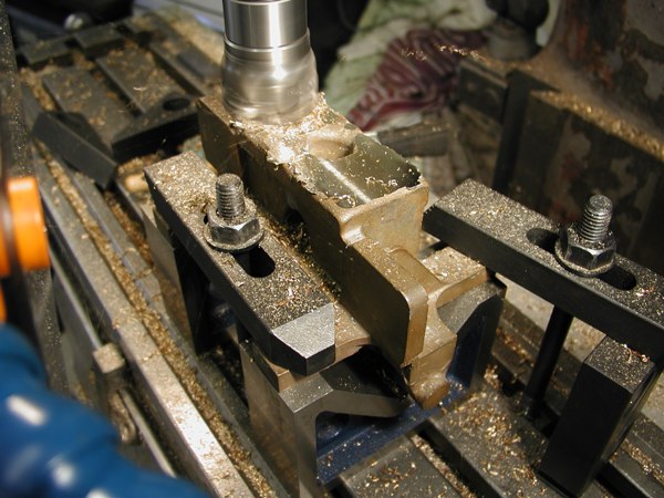
So off to the mill and it was set up to machine to width, done slightly differently because of the size I could only do one side at a time.
Machining the first side
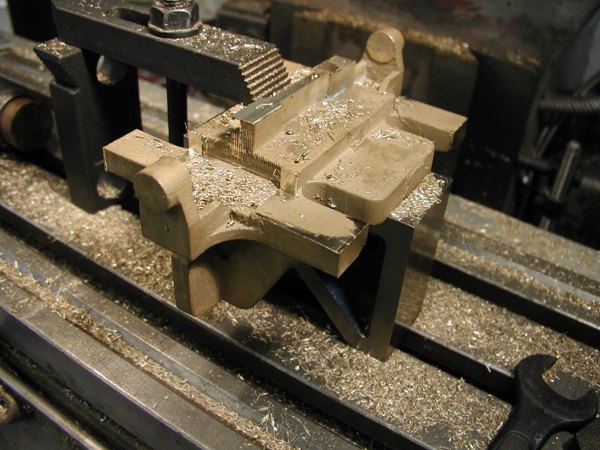
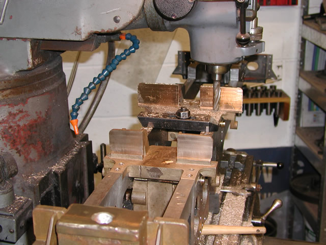
The next job was to drill the two holes for the brake shaft retaining bolts. Not quite that easy due to the size of the casting. By using an extension I was able to get the milling cutter in to cut the recesses where the nuts sit.
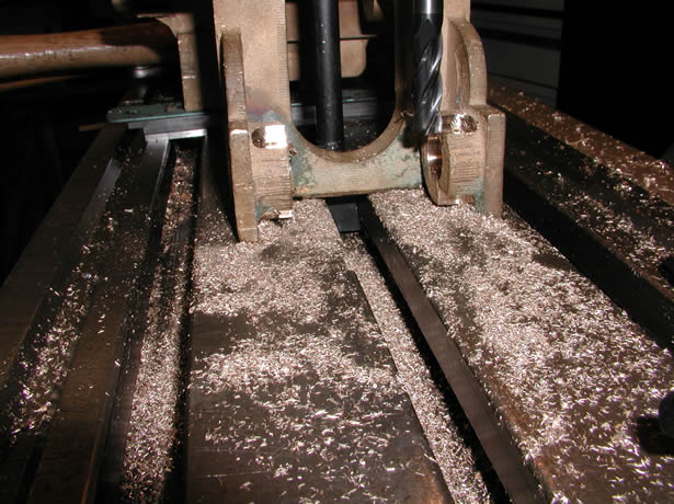
Cutting the recesses for the nuts on the shaft retainers
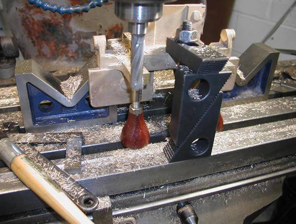
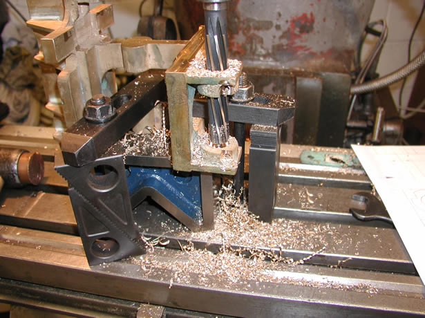
Set up to drill and ream the shaft hole
Measuring off the two square edges of the boss where the brake shaft fitted using the DRO I was able to establish the center of the brake shaft. Then I center drilled, and pilot drilled the hole through both boss's following up with a reamer to bring the hole to size.
 .
.
Two shots showing the drilling and reaming operations on the brake shaft boss's
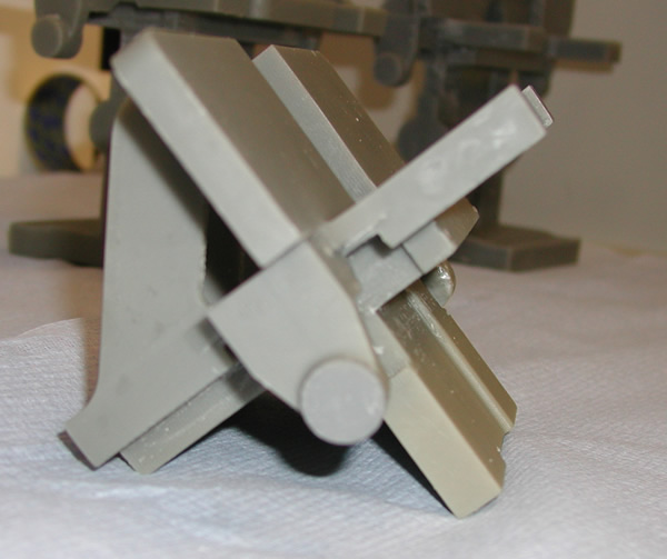
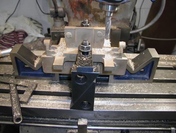
Final job on the bracket before fitting to the frame and match drilling the fixing holes was to cut the inside face of the brake hangers. To do this I set the bracket up in the mill. Then using a slitting saw touched onto the side face and moved the table down until I had the correct dimension from the frame face, obviously allowing for the cutter thickness,
Although because of the camera angle this all looks to be on the slide it was square... trust me.
The frames had cut outs where the beams were to sit which had been machined into the frame material when they were bolted together as a matched pair.
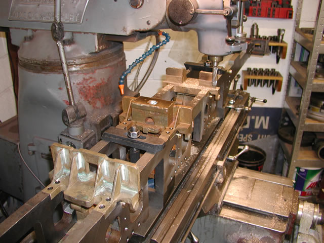
So once the frames where parted I needed to make sure that the cross beams fitted into the locations and that the frames were square so I did not induce any errors wit the frames being slightly out of line, for and aft. To do this I decided to work everything off the frame pedestals. These were the datum's that I had worked everything off but that was when the frames where flat. I now wanted the frames to be on edge and parallel. To accomplish this I fitted two blocks to the mill bed and machined them to the correct width and distance to fit the main pedestal and one of the pedestals at each side. These would be either the front or intermediate and were all the same size which made things easier.
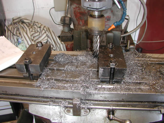
Blocks being machined on the mill
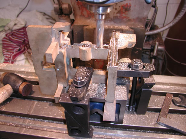
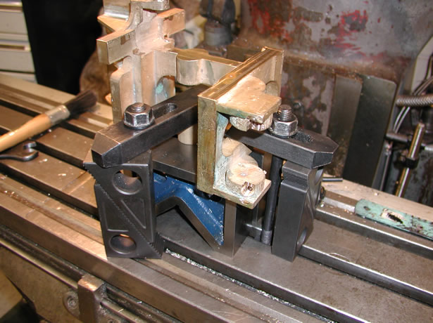
Once the blocks were machined to size I could fit the frames to them and then locate the cross beams in the slots knowing that the frames would still be parallel once the cross beams were bolted up.
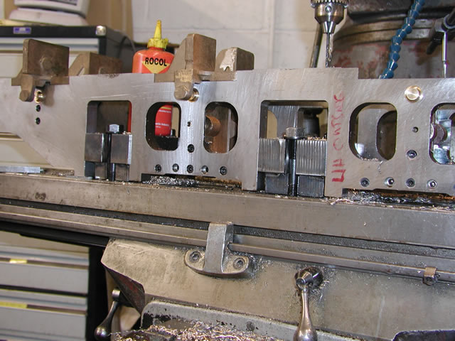
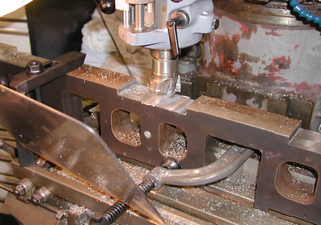
Cross beams temporarily fitted with cross blots and ready to drill the top face.
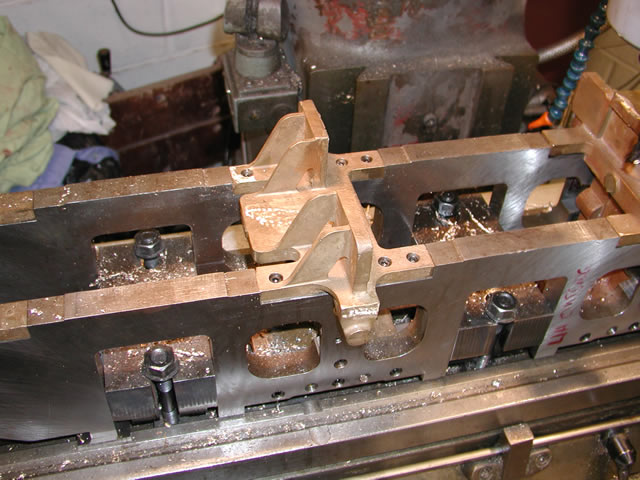
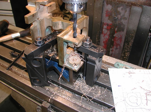
Each cross beam was bolted up horizontally then the top holes were drilled through the bronze into the frame slot with the tapping drill. Then this was followed up with a clearance hole and finally a rebate to accommodate the head. Later I will fill the holes with body filler.
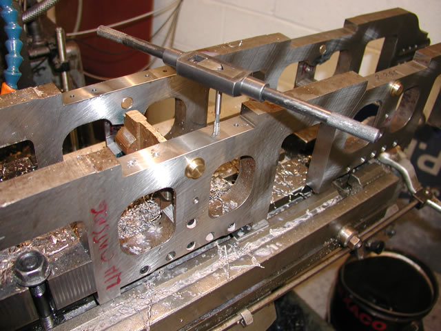
Tapping the holes
After I had the two central beams fitted and bolted up I removed the blocks and placed the frames on v-blocks to drill the front and hind beam.
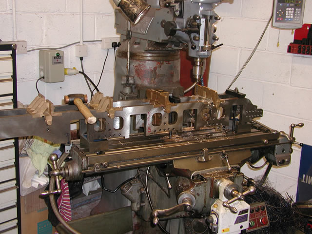
All frame cross beams fitted to the frames.
Once the cross beams had been bolted up I now had a fairly robust structure that I could work on without too many worries. The next job was to machine the face of each cross beam to position and height. Once again I worked everything off the main driver pedestal using the digital edge finder. Once I had established the center of this point I was able to machine each beam to position relative to the center and also height from the top of the frame
Machining the front crossbeam
Close up of machining the beam, the beam prior to it has also been fully machined.
In the above picture you can see on the beam that is complete how the face is machined and there is also a step left on the face as a register to locate the cross beam plate. the plate bolts to the face of each beam and provides support in this case for the motion girders.
All faces machined
The last thing to do on the cross beams was to drill the horizontal holes for mounting the plates. to do this I made a jig so I could hold each cross beam in a horizontal plane and I will show that later