

Click on the loco to go back to the 25NC home page
25NC Front Truck
Where to start? Well according to Keith Wilson who writes in the Model engineer, make something people can recognise and you can cart around. Well he recommends the front truck so it seemed like a good point for a kick off.
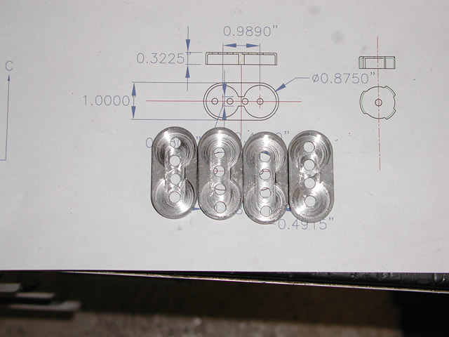
Click here to have a look at the detailed drawings.
So just break myself in I thought a bit of easy turning would be in order so a start was made on the wheels

After roughing out the basic shape I mounted the whole thing on a mandrel to allow finishing of the OD then shrunk on a steel tyre. I found the gas cooker on nine would expend the tyres by about 10 "thou".

After getting all the wheels heated up and the tyres shrunk on the next job was turning the outside tread profile. For this I decided to make a mandrel and do all the turning with the wheels mounted on it


Well after the easy start on the wheels I decided to make a start on the front truck frame. The frame had been designed as a 3 part iron casting. I wish now I had pushed the pattern maker to make it in one piece But at the time it was a more cost effective solution and Terry was a bit more comfortable making it in three pieces. Looking now at the job he made of the trailing truck pattern, a one piece masterpiece I don't know what he was worried about, still more of that in the future.
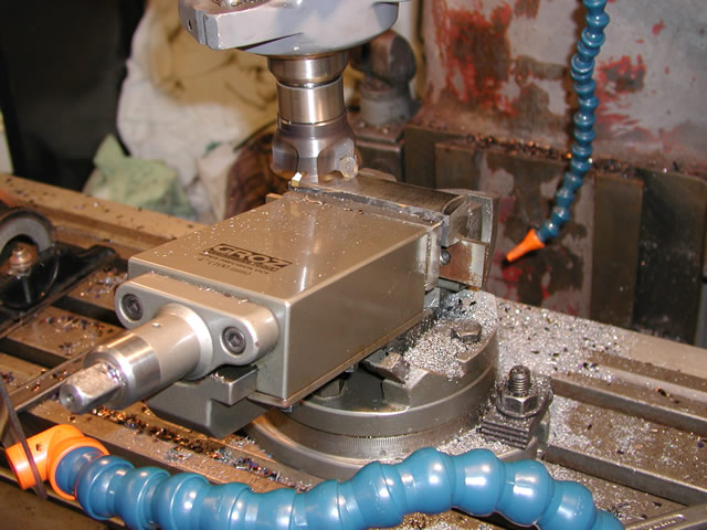
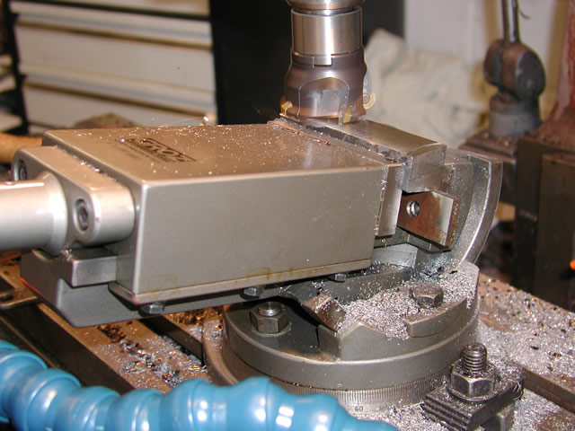
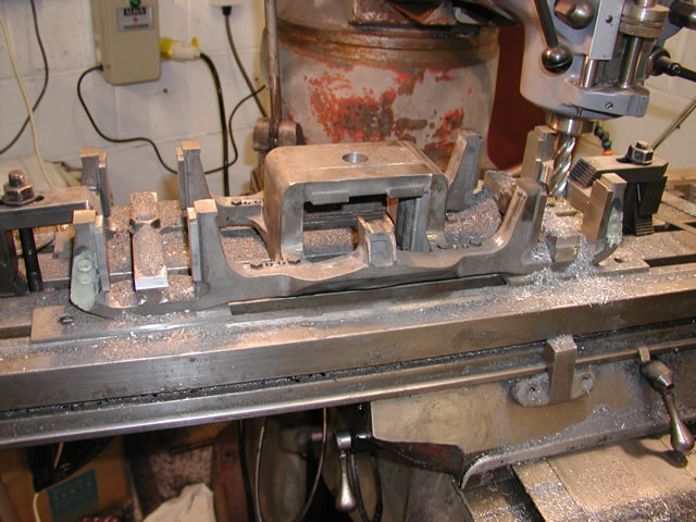
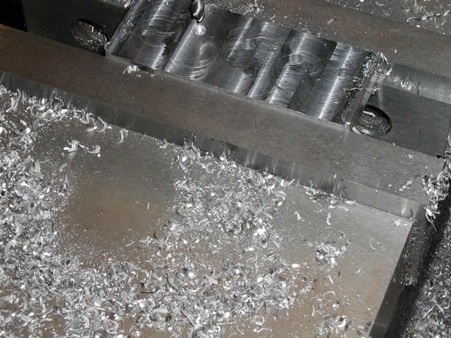
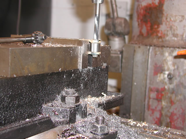
The truck frame was designed with four pockets and corresponding arms that fitted to the pockets. So as a start I need to mill out the two pockets per side frame. This was relatively easy just getting the thing set up to be as square as possible being the only time consuming part.
I used a cobalt roughing cutter to get through the surface hardness of the casting and I must say the cutters turned out to be a life saver where I could not get a tipped tool in to do the work. In retrospect this pocket idea was a compromise from the start there was a better way to design this but that is with the benefit of 20-20.
The next stage in the process was to machine the center bolster, for bolting the two side frames to it. I try whenever possible to do everything in as few settings as possible. This reduces the margin for errors but generally makes some of the machining a bit of a challenge.
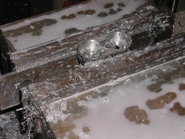
To start with I clamped the casting onto the table and drilled the pivot clarence hole in it. This would also provide me with a suitable hole to clamp the casting down in future operations.


Once the hole had been drilled I then turned the casting over to take a skim off the top face to again provide a datum to work off.


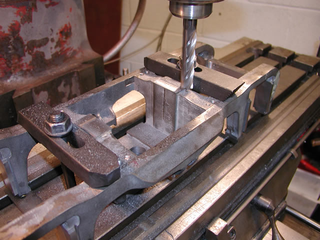
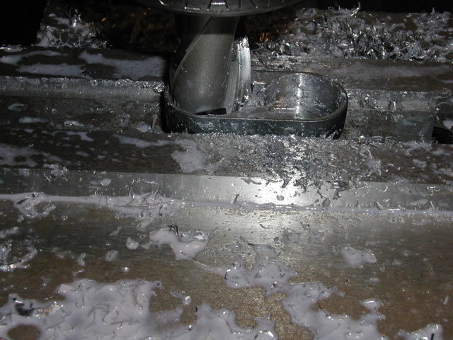
Once the casting had been turned over i set it up square in the X and Y directions and machined the wings that bolt into the pockets. This had to be done at fairly steady feed rates due to the tool extension I used, to enable it to be machined in one setting. At this setting though i could get both the overall width and length set as well as the pocket width and length..


The last operation was drilling the holes for the bolts, I drilled tapping size first as i was going to match drill through into the side frames. Once the drilling was done i was ready to drill and bolt up the frames to the bolster.

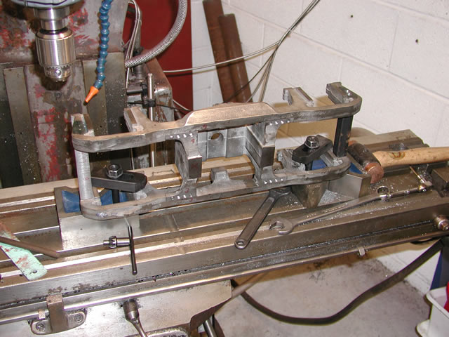
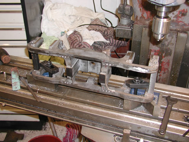
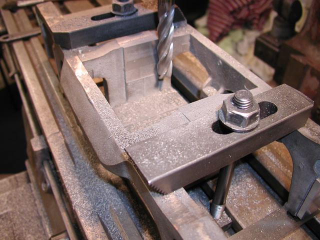
So the next step was to temporarily clamp the side frames to the center drill though with a tapping drill and clamp the frames up.


Not the most elegant of solutions but it worked well. I fitted a bolt to each side then drilled the rest of the holes before drilling out the bolster holes to be a tight fit on the bolts.
As I said in the frame section the format of the page is going to change as it makes it a lot easier for me to code the page.
The full size frame had two cross members between the forward pedestals. As the frame had been cast in three pieces it was necessary to replicate these using mild steel bar.
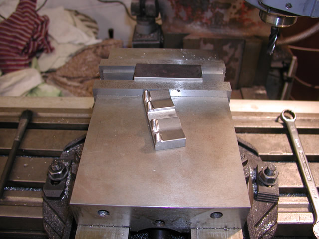
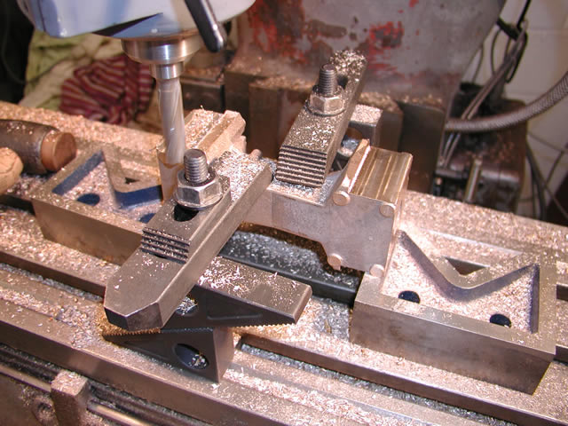
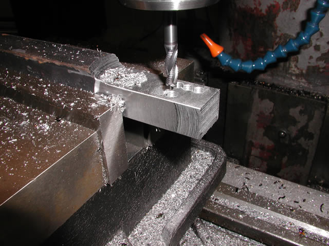
The cross members stated off as two pieces of black bar which were milled to form a slight taper to the front side
Two shots of the milling operation and the taper being formed on the front side.
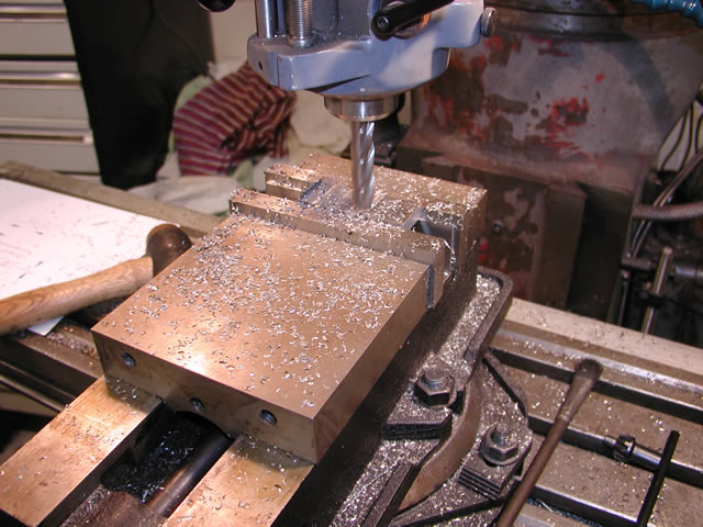
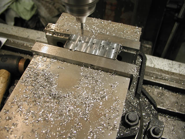
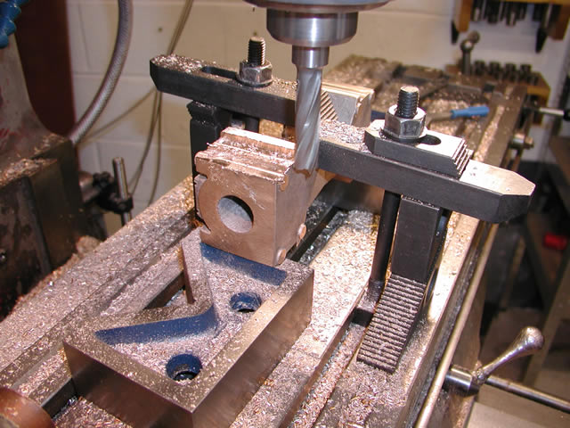
Once the bar had been machined to shape and also length the frame was set up on its side to drill the fixing holes for the blocks
Drilling through the frames to spot the blocks prior to tapping.
Although you cannot see it in the above snap the frame had pads cast on where the blocks would fit so with the pads machined to just proud of the frame it was easy to get the blocks the correct length. Just a slight tap fit into the frames which made it easy to spot through the frames to locate the holes for tapping in the blocks.
Countersinking the bolt holes for the cap head screw.
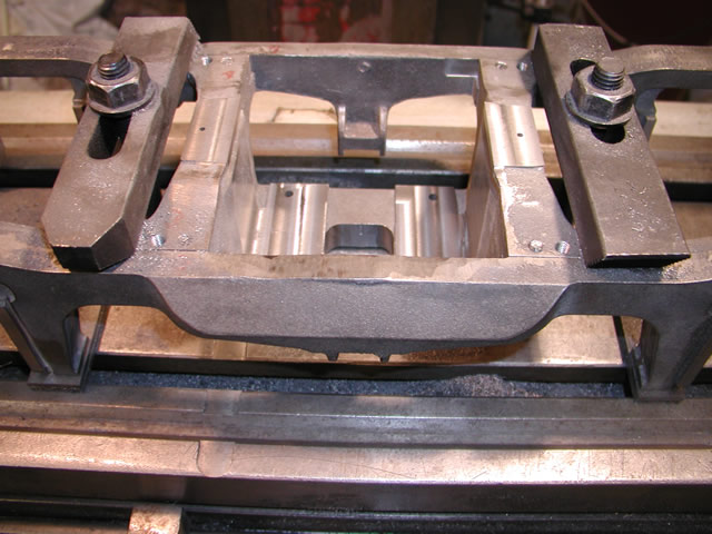
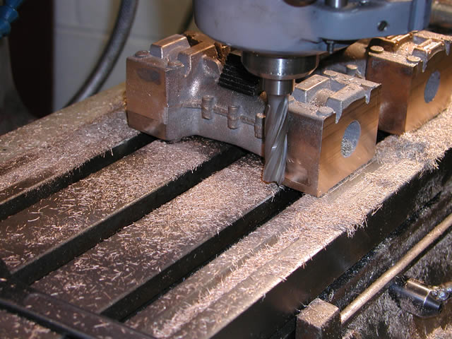
Once the frames were drilled through into the blocks, the frames were opened out to take the heads of the cap bolts as eventually the holes would be filed up to disguise the construction method. So we now had the frame in one piece and it was now time to sort out the pedestal liners or horn blocks as us Brit's call them. So first thing was to sit the truck on its back, this would enable all major machining operations to be done at one setting. To do this I had purchased a long series cobalt cutter of 16mm diameter. This had a flute length long enough to machine the faces of the horn blocks to their full depth.
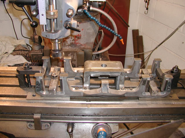
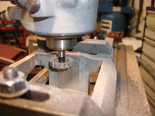
Taking a cut of the bottom of the horn blocks
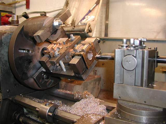
First job was to face the bottoms of the horn blocks this allowed all the other measurements to be offset from them. I then used a digital edge finder to center the casting and zeroed the digital read outs for the X and Y axis. As all the measurements would work away from these datum points
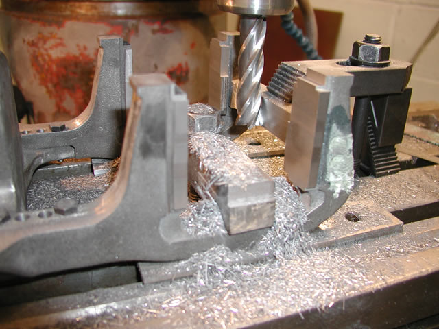
Cutting the faces
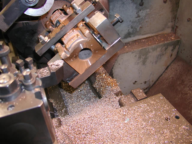
in the above shot you can see all the machining areas needed on each axle pedestal. I started by machining the outside and inside faces. The truck uses cannon box axle boxes so the outside face is the least important. The inside faces though had to be accurate.
Then using the datum of the center of the frame I moved out so the cutter was on the center of the axle then machined away form it on each side to get the two faces the correct width to take the axle box. This again was an important dimension to adhere to and I took only very light cuts towards the end to ensure the dimensions were correct.
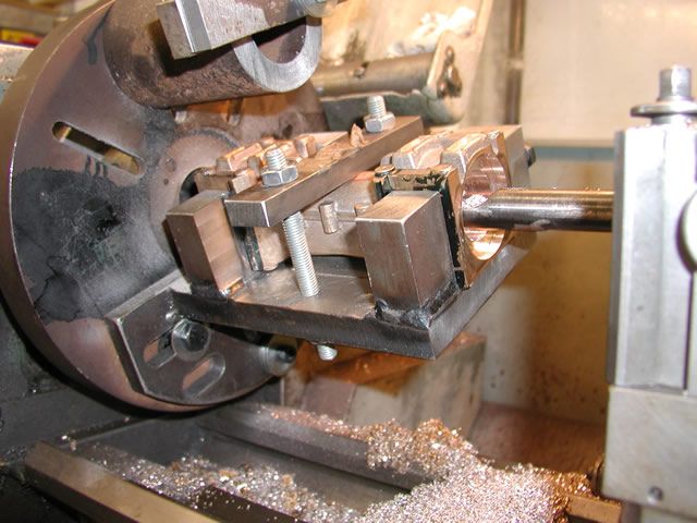
The last job was to machine a step on the feet for the pedestal binder to sit in. Again you can see this step in the shot. shown below. You can also see the cut line on the face as I worked my way down with the cutter.
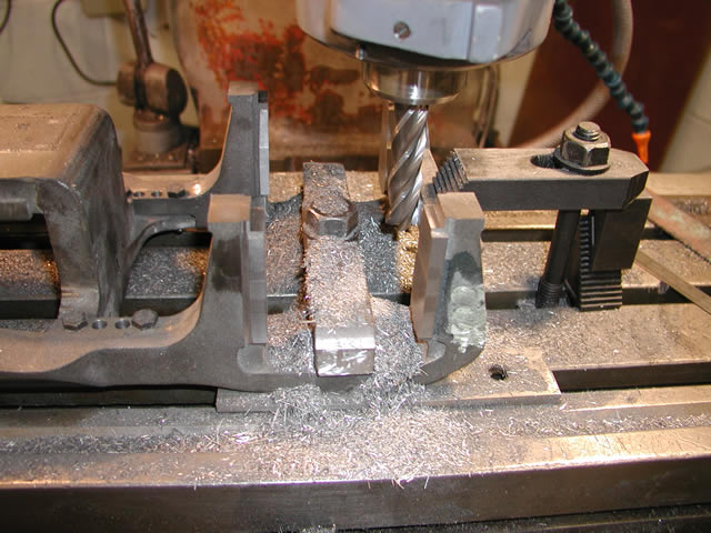
You can see the filler where the bolt holes were in the above shot.
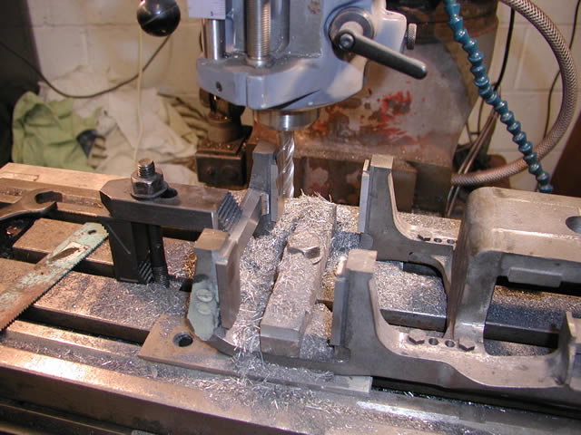
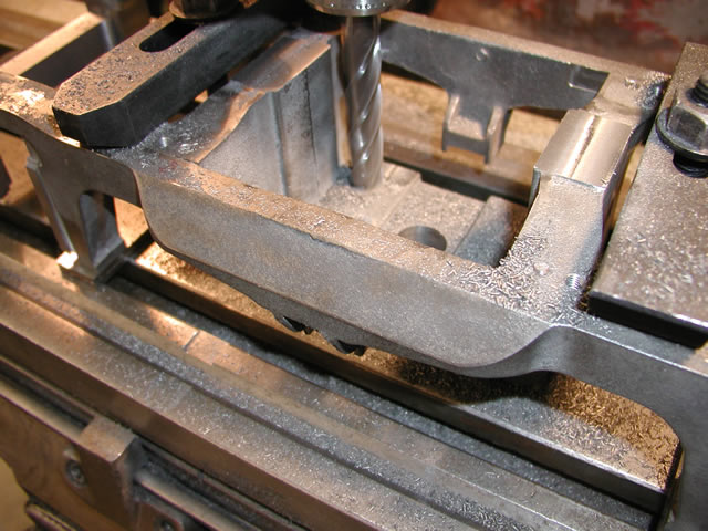
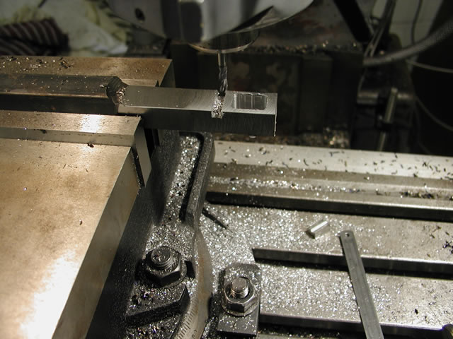
The last job on the frame was to undercut the black bar blocks to represent the original shape of the casting.
You can just see the radius formed behind the cutter on the end blocks.
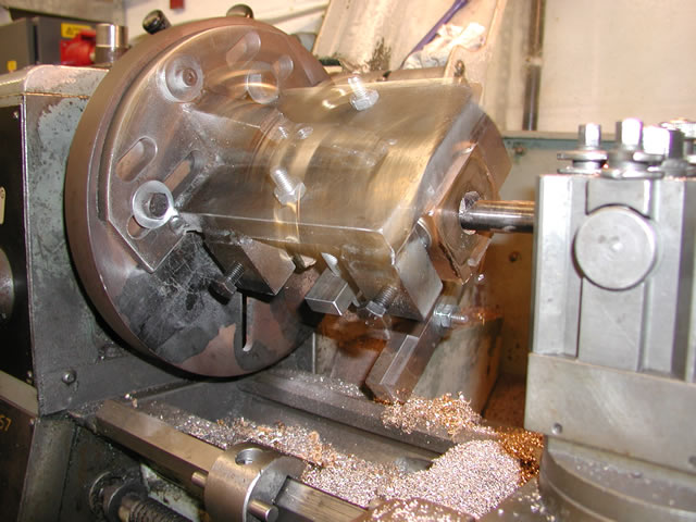
With the frame now in one piece it was time to flip it over and machine the top side for the centering device and bolster recess.. First thing was to set the frame square off the previously machined pedestals. I then took a cut off the two face where some L shaped plates fit to retain the bolster.
Set up on mill First cut across retainer plate face
Machining the bottom faces for the rocker plates
Once this top face datum had been machined I then machined the two lower faces of the bolster pocket. These faces sit proud of the bottom face and needed to be machined both to the correct height and along each edge so the two rocker plates would sit nicely on them.
After that both end face were machined to width, then a slot was machined in each face to hold the top retainer plate. This plate hooks under and into the face. I would think this takes the load off the bolts in real life.
Machining the retaining plate recess
Bolster finished with datum holes drilled
Next job was too machine up the inclined plane rocker plates. These plates are very similar in concept to the rockers fitted to the cradle and trailing truck bogie. However in this case they are on the inside of the truck not the outside. But both rely on an inclined plane returning the roller or rocker to the center with the help of the springing.
Rockers fresh from the CNC machine
The plates were quite a complicated shape and at the time I was a bit confused about how to machine them. So as usual I took the easy way out and had them CNC machined. This was to produce the teeth and planes on the working side of the plate. I elected to do the rest of the machining for fitting to the truck.
Machining the bottom face of the plate
It was probably representative of my knowledge at the time but I would not CNC them now as it would be relatively easy to fabricate them or perhaps have them rapid prototyped. Also I lost touch with the guy who did the CNC machining for me or at least he stopped answering e-mails so I assume he decided to trade elsewhere or get out of the modeling game altogether.
Machining the underneath was a relatively easy job just producing a slot then drilling the holes for 5 rivets that held the plate to the truck frame.
Last job drilling the rivet holes. I then turned the plate over and recessed the holes for the countersunk rivet heads.
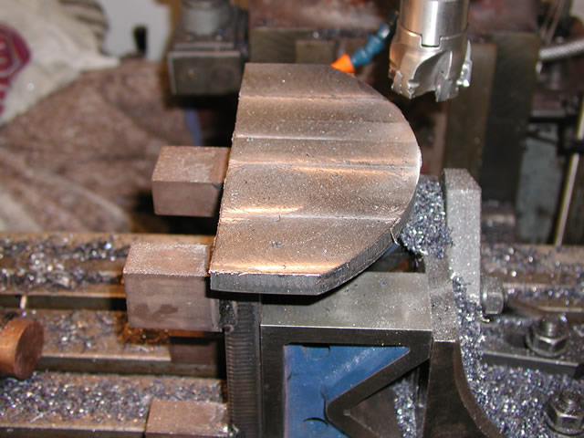
Next job was to machine the rollers, these were bronze castings from rapid prototypes with the matching holes formed in them, so only needed machining on the outside and ends. There were bosses at each end where a small retaining plate fits to keep them correctly spaced as they roll up and down the track
Machining the rollers between centers. Forming the boss on each end.
The completed roller sitting on the rocker plates
From the snap above you should be able to make out the inclines and rocker teeth. The shot below shows the finished rocker plates riveted into the frame with one of the rollers sitting in position. There are two opposing rocker plates riveted to the bolster fitted to the frame which will be described later. The bolster fits to the bottom of the cylinder block and the block was still some time off when this work was done
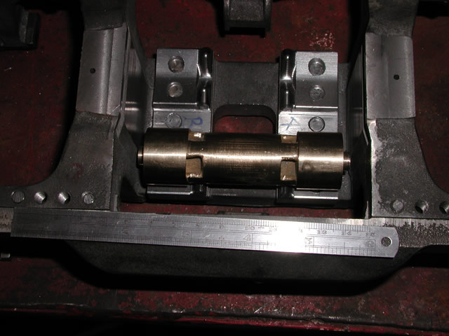
Plates and roller fitted to frame.
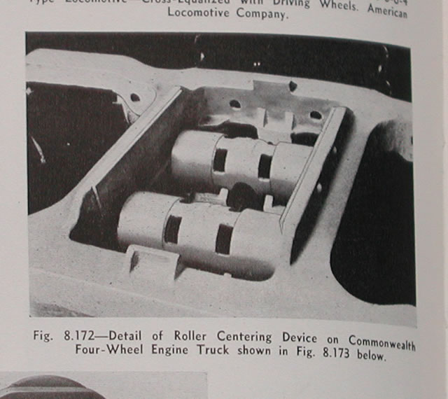
Lastly an illustration I scanned from the 1947 railroad cyclopedia of a commonwealth truck that is virtually the same design as the 25NC front truck.
So once the main casting assembly was finished it would be time to tackle the cannon boxes. These were a one piece casting in bronze. The critical factor being that I needed to bore a hole at each end for the bearings and how to do that did give me a few sleepless nights till I came up with a suitable solution.
Machining the back face of the jig prior to slotting for the face plate
First job was to face up the boxes on one edge and the front face to give me a datum to work from. I also machined a grove on top where the spring brace plate fitted. For some reason I did not take any snaps of this operation but as its essential the same on the driver cannon boxes you will be able to see it there in the future.
Machining the front and side faces as the datum's to work from
Once the face and side was machined I was then able to machine away from these datum’s and get the depth and width of the faces machined on one side.
Cutting the first pendant face and edge
After that it was just a matter of turning the boxes over and repeating the process to produce the correct width of face and the correct distance between the pendant faces. As with all first times I machined them all a bit on the neat side and had to spend some time draw filing them to get a good a fit.
Box turned over and machining the second side
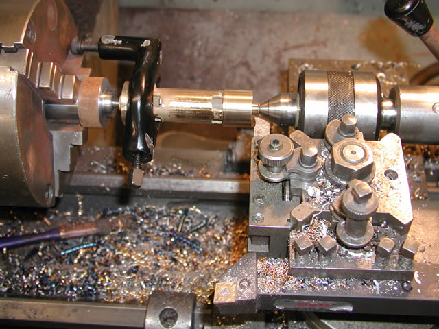
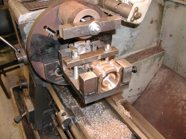
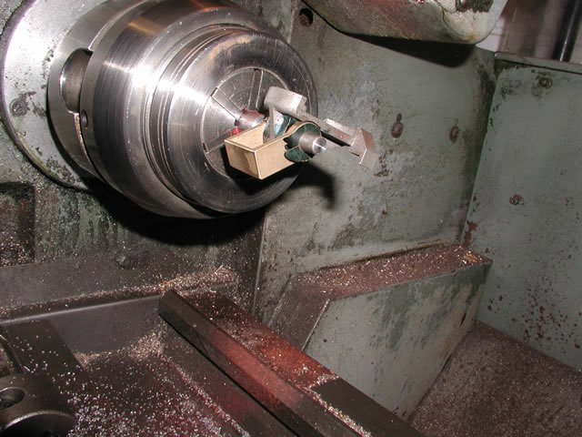
Once the basic machining of the boxes was complete I then had to work out how to bore them out and make sure both ends were in line. To do this I made a jig that would fit the Colchester lathe face palate. The big idea was as I had already machined the faces I could set it to height and centre using a target card. Then to do the other end just remove the locking bar across the top rotate the box through 180deg and machine as before.
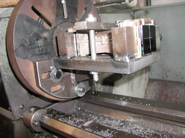
The jig set up on the colchester face plate. Plastic card blued up and center target point scribed onto it.
Using the target I was able to loosen off the holding bolts and reposition the jig until it was correctly centered on the target then tighten up the bolts to ensure both ends would be the same.
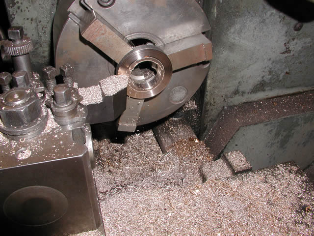
Facing the end to length.this brought the box to the correct overall width and boring of the holes could start
I bored the axle bore half way from both sides, then bored the bearing bore next
Whoa too much coffee
Finnish cutting the bearing cap bore
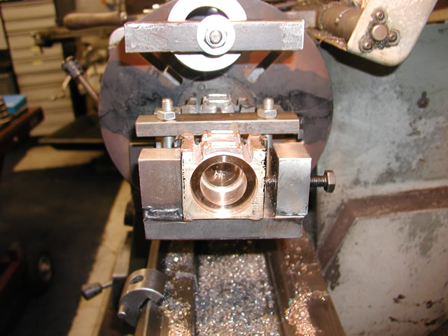
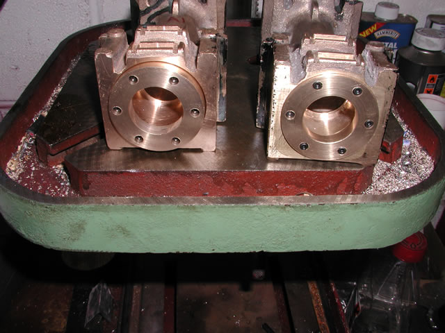
These two shots of the completed bore show how the jig works to get the other end in line you release the top bar clamp, end for end the casting then re tighten the two side bolts to hold it against the jig side face then pop the top clamp back on to hold it down.
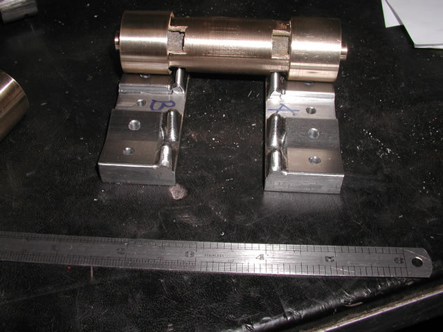
Once this was done I made some end caps. The main purpose of the caps is to extend the face to the correct width for either 7.25 or 7.5 gauge. As the bearings are a press fit and also have a dirt seal fitted integrally so really the caps are only glorified spacers.
Machining the bearing end cap
Boxes with caps temporarily fitted
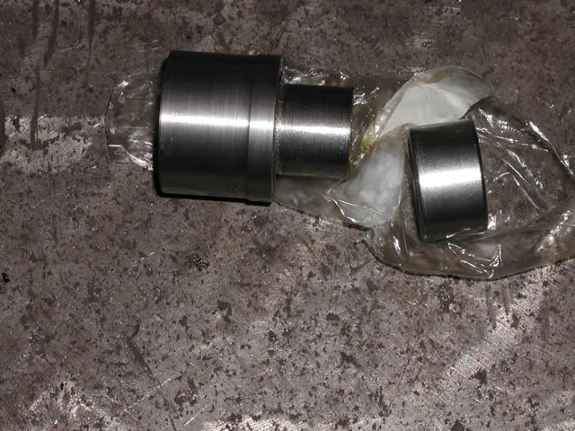
Little jig made to push the bearing into the boxes
Pressing the bearings in on the press at work
Well there is not much more to add to the front truck, as I don't have that much more in the way of illustrations. Generally what was left was the suspension which was a mixture of CNC laser cutting and a bit of good old fashioned filing.
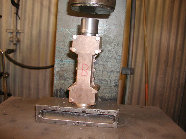
First thing to tackle was the spring buckles and springs. I did not have any material of the right size so cut some black bar down to size. Then used a cutter to cut the basic shape of the buckle out. All that remained was to use a file and square out the corners for the spring leaves.
Once the basic shape was cut I just ran the cutter down the back side to finnish the buckle to size.
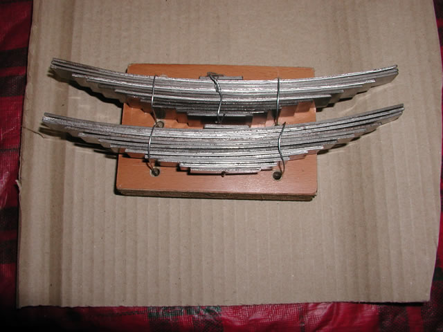
I bought some annealed spring steel of the scale thickness and width Then using a set of rollers rolled them to the correct radius. Once that was done I sent them off to be hardened
Next job was the spring hangers these were rapid prototyped in cast form wax in the states then cast in sheffield only needing the pin hole drilling and reaming to finnish.
Side control is provided by coil springs working in spring cups and a fancy buckle. The buckle was CNC'd by a guy who has disappeared but he did some great work for me when he was around. All I had to do was ream out the pin hole and in this case fit an oil-lite bush.
Two shots of the cups which were laser cut then bored out to suite
All cups machined and ready to bolt to the frames
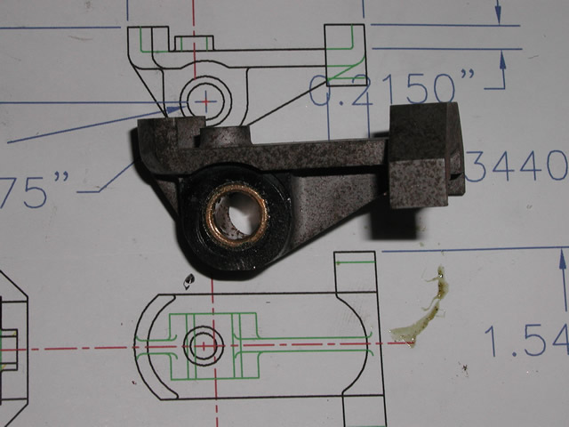
Above the bottom spring cup CNC machined then fitted with an oil-lite bush
Testing the cross pins for fit in the spring hangers and buckle
Well that is about all I have as I said I don't have that much photographic information on the spring rigging for the front truck. I purchased 8 coil springs to finnish off the job. I have an idea they will be too light and a much stronger spring rate will be required. Only testing will determine if my guess was correct or not.
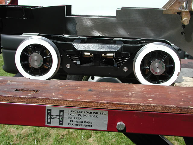
The only shots I have of the front truck are from a show I did some time ago. So although not that good I hope give you an idea of the finished object. One comes courtesy of Trevor Heath who took the shot at a show in Reading in the early days of construction.
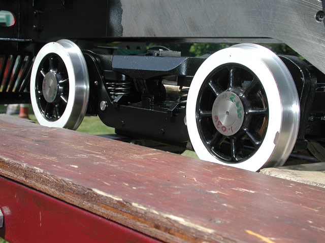
Two shots of the almost complete truck
Well that about cuts it for the front truck I still have the bolster to make but that is still waiting a little bit of design tweaking.